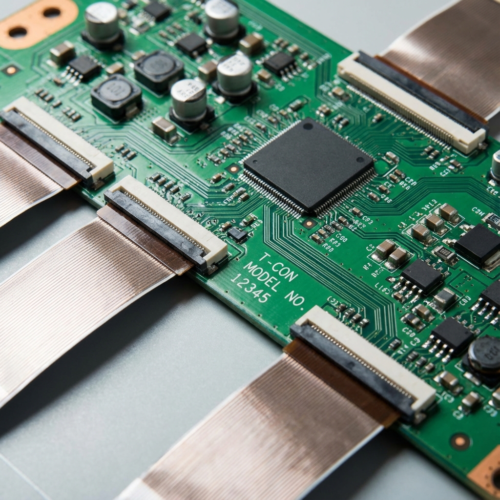
TCL Roku 65" QLED - T-Con Board Failure with Vertical Lines
TCL Roku TV with vertical lines and color distortion. T-Con board power management IC failure diagnosed and replaced without full panel replacement.

Symptoms
- Vertical colored lines across entire screen
- Distorted colors (purple/green tint)
- Lines are consistent (don't flicker)
- Picture is visible but heavily distorted
Diagnosis
Vertical lines on an LCD/QLED TV usually indicate either a T-Con board failure or a bad panel. The key diagnostic is whether the lines are consistent or change with content. In this case, the lines were fixed in position and didn't change, pointing to T-Con. Removed the T-Con board and measured the voltage rails with a multimeter. The T-Con requires several voltages: typically 12V input, then internal DC-DC converters generate 3.3V, 5V, and various gate voltages (15V, -7V, etc.). Found the 5V rail reading only 2.1V - way out of spec. Traced this to the PMIC (Power Management IC) which was running extremely hot (80°C+). The PMIC's internal DC-DC converter had failed, likely due to a shorted output capacitor or internal transistor failure. Replacing the PMIC would restore the 5V rail and fix the display.
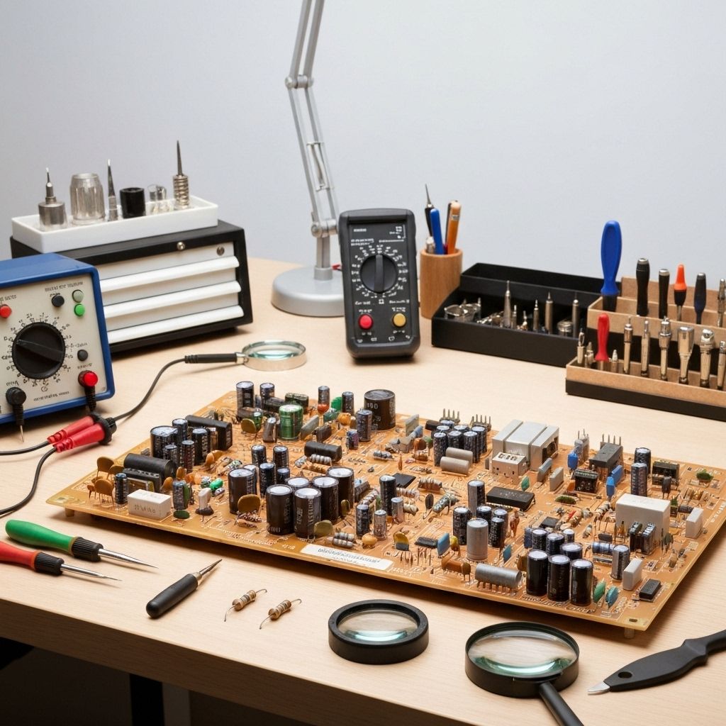
- Multimeter
- Hot Air Rework Station (essential for BGA/QFN work)
- Soldering Iron with fine tip
- Flux Paste (no-clean)
- Solder Wick
- Tweezers
- Thermal Camera or IR Thermometer (for finding hot components)
- Kapton Tape (heat-resistant)
- T-Con PMICModel-specific (check board markings)Power management IC - usually QFN or BGA package
- Ceramic Capacitors10µF 16V (preventive replacement)Output filter caps near PMIC
Repair Process
Remove and Test T-Con Board
Power off and unplug the TV. Remove the back cover and locate the T-Con board (usually at the top of the panel with ribbon cables going to the screen). Disconnect the ribbon cables carefully - they're fragile. Remove the T-Con board screws. With the board out, power it up on the bench (connect 12V input and ground). Measure all voltage rails with a multimeter. In this case, the 5V rail was at 2.1V.
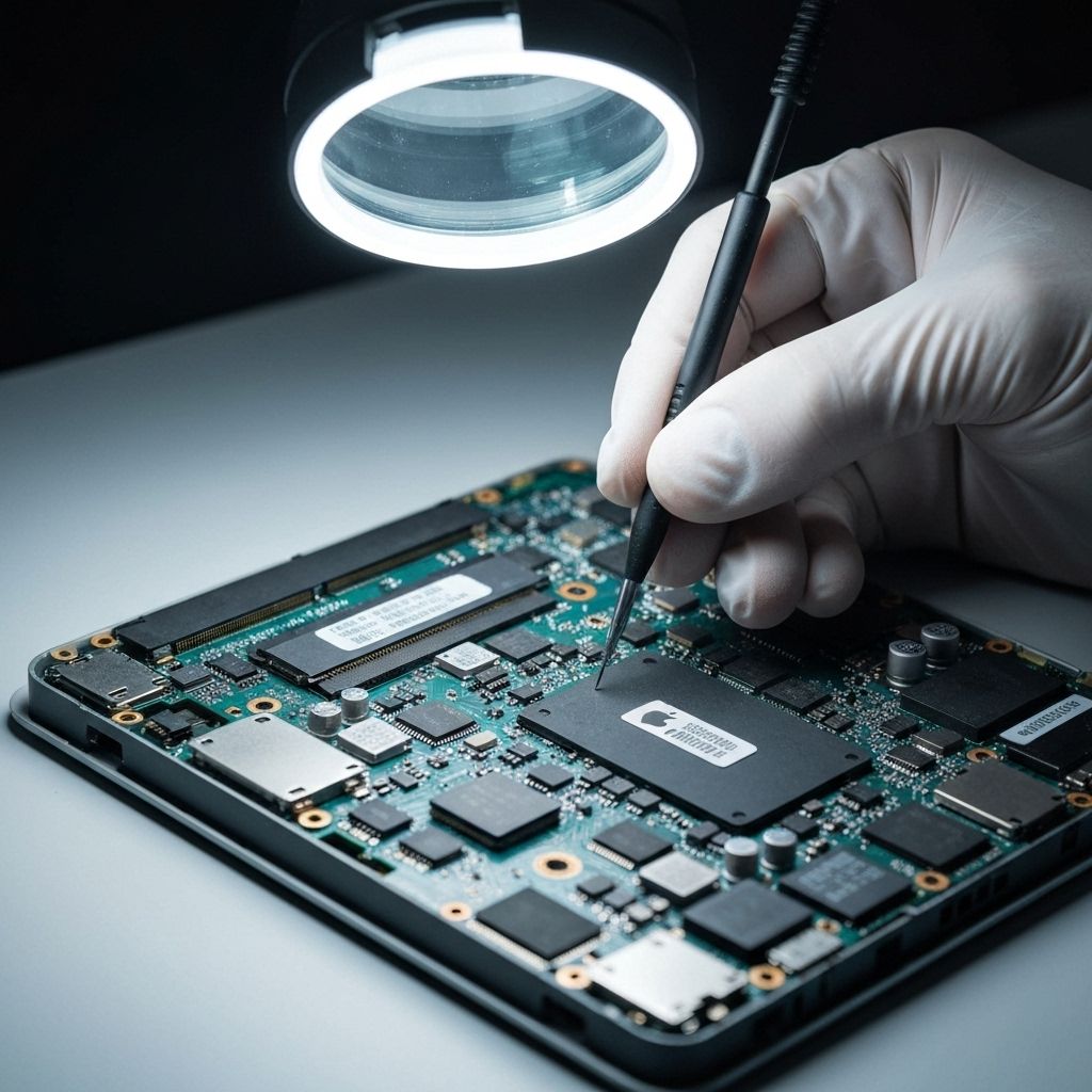
Identify the Failed PMIC
Use an IR thermometer or thermal camera to find the hottest component on the T-Con. The failed PMIC was running at 85°C while everything else was 40-50°C. This confirmed it was working hard but failing to regulate. Note the IC part number (usually printed on top or check the board schematic if available).
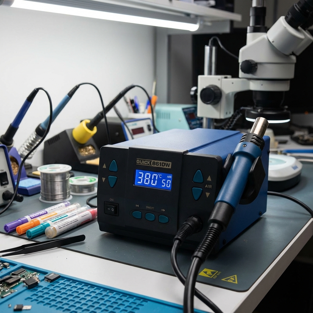
Remove the Failed PMIC
This is advanced work. The PMIC is usually a QFN or small BGA package. Protect surrounding components with Kapton tape. Apply flux liberally. Use hot air at 350-380°C with medium airflow. Heat the IC evenly in a circular motion until it lifts off (usually 30-60 seconds). Don't overheat or you'll damage the PCB. Remove the IC with tweezers.
Clean Pads and Install New PMIC
Clean the pads with solder wick and flux. The pads should be flat and shiny. Apply a thin layer of solder paste or flux to the pads. Position the new PMIC carefully - alignment is critical. Use hot air to reflow the solder (350°C). The IC will 'snap' into place when the solder melts. Let it cool naturally.
Test and Reinstall
Power up the T-Con board on the bench and measure the voltage rails again. The 5V rail should now read 5.0V ±0.1V. All other rails should be within spec. If good, reinstall the T-Con board in the TV, reconnect the ribbon cables, and power on. The vertical lines should be completely gone and colors should be accurate.
Conclusion
T-Con board repairs are often overlooked because many technicians assume vertical lines mean a bad panel (which costs $400-800 to replace). In reality, T-Con failures are common and repairable. The PMIC cost $3-5 and the repair took 90 minutes. This saved the customer from an expensive panel replacement. Key lesson: always test the T-Con voltage rails before declaring a panel bad. Most T-Con failures are power-related and fixable.